
StarTrak, a freeware program for amateur astronomers
Welcome to the homepage of StarTrak, a freeware program for amateur astronomers. StarTrak runs on the Psion 3, 3a, 3c and 3mx range of handheld computers. Its purpose is to help you find and track the positions of planets, stars, galaxies and other objects of the night sky : www.pleine-lune.org
What is StarTrak? What does it do?
StarTrak is a computerised database, containing information on the planets, all the Messier objects, as well as a number of other objects in the sky. For any object in its database, StarTrak can give you that object’s position in two formats:
- RA (hours and minutes of Right-Ascension) and Dec (degrees and minutes of Declination) coordinates
- Altitude angle (number of degrees and minutes upwards from the horizontal) and Azimuth angle (direction in degrees and minutes from true North).
Thus if your telescope has either RA/Dec or altazimuth setting circles, it’s easy to point the telescope at the object of interest. This makes StarTrak suitable for both equatorial-mount telescopes and altazimuth mount telescopes (such as Dobsonians).
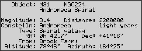
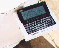
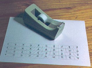
The above figure shows a typical screen of information on a Psion computer running StarTrak. It shows three alternative names (M31, NGC224, Andromeda Spiral) for the same object, together with other information. If you were running StarTrak now, looking at the Andromeda Spiral, it’s very unlikely that the altitude and azimuth readout would show the same values as in the figure - in fact, as the Earth spins on its axis and orbits the Sun, the altitude and azimuth of any celestial object are constantly changing. StarTrak updates its altitude and azimuth readout every second. It can do this because it knows the current time (from the Psion’s clock), and from this can calculate the Earth’s position in space. StarTrak also knows the latitude and longitude of your chosen observatory, and the RA (Right-Ascension) and Dec (Declination) coordinates of each celestial object in its database. StarTrak is programmed to use this information to calculate an object’s altitude and azimuth (as seen from your chosen observatory), and to keep re-calculating the altitude and azimuth, which change with the passage of time as the Earth moves through space.
The StarTrak database contains a relatively small number of objects (the planets, all the Messier objects, plus a few others), but it is very easy to add objects of your choice. To add an object to the StarTrak database, the minimum information you need is the object’s name and its RA and Dec coordinates. StarTrak will then be able to tell you where to point your telescope to find that object.
What StarTrak doesn’t do
StarTrak doesn’t display a view of the night sky, and is not intended to replace star charts. Rather, it is designed to be used with a star chart to help you find the object of interest. Point the telescope in the right direction with information from StarTrak , and compare the view through the telescope with your star chart to identify the object of interest. Of course, in many cases it will not be necessary to use a star chart - from the view through the telescope, the object you are seeking will be obvious.
The present version of StarTrak doesn’t show the positions of the Sun, Moon, asteroids and comets.
The present version of StarTrak ignores
- atmospheric refraction
- precession (this is the gyration of the Earth’s axis over a period of 26000 years, caused by the gravitational effects of the Sun and Moon)
- nutation (the slight wobble in the Earth’s movement caused by the variation in the relative positions of the Moon and Sun)
since these effects cause only a fraction of a degree change in altitude and azimuth.
StarTrak is particularly well suited to telescopes with Dobsonian mounts. If your telescope is a Dobsonian but doesn’t have azimuth and altitude setting circles, see Making Setting Circles.
Disclaimer
The information given at this website describes the freeware program StarTrak from ST Software, and bears no relation to any other product or program of the same name.
Feedback and technical assistance
Your comments, questions and suggestions on StarTrak and this website are welcomed - just send an email by this link:
Your email address will not be passed on to anyone, nor will it be added to any email list, but will simply be used to respond to your query.
It would be interesting to know from which part of the world you observe the sky, so please include this information if you have time. Thank you!
StarTrak - featured in an issue of Astronomy Now- the UK’s leading magazine for amateur astronomers.
StarTrak: some photos showing 'scopes with altitude and azimuth scales
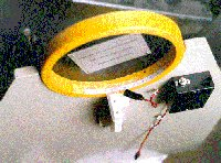
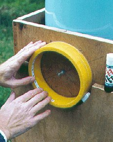
Altitude scale and azimuth circle on CAA’s (Cambridge Astronomical Association’s) half-metre Dobsonian. The black box holds rechargeable penlite cells which power red LEDs to illuminate the scales.
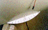
Close-up of the altitude scale on the CAA half-metre Dobsonian This scale is paper (printed from the program you can download from this site) stuck to the plastic bearing tube with PVA glue.
Close-up of the azimuth setting circle on the CAA half-metre Dobsonian. This setting circle was made from 3mm thickness plywood.
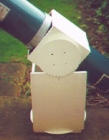
On this scope the altitude bearing was of a small diameter, so a large circular altitude circle was fitted (rather than the usual linear scale fitted to the inside of the bearing tube). Both circles were cut from 2mm MDF and given a few coats of quick-drying water-based primer and water-based gloss paint.
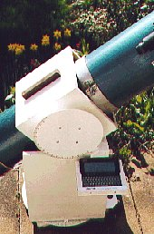
The same telescope was later adapted to allow left-hand or right-hand use, and the Psion computer was mounted on a removable platform.
Close up of the Psion computer on its removable platform.
StarTrak: FAQs
- How accurate is StarTrak?
The altitude and azimuth readouts from StarTrak are accurate to within a small fraction of a degree (provided you have the correct RA and DEC for the object, and the Psion’s clock is accurately set). Other factors tend to be more important; these include (for a Dobsonian):
Is the telescope level?
Are the two altitude pivots at the same height?
Is the azimuth circle centred accurately?
Ironically, the runaway success of the Dobsonian design is largely because it does not need to be precisely engineered. Despite this, StarTrak will work very well with most Dobs - you will be very unlucky if the star you are seeking is more than a degree out from its expected position on the azimuth or altitude scales.
- Some computerised databases contain over 12000 objects, whereas StarTrak’s database contains only about 250. Why is this?
Part of the philosophy behind the design of StarTrak was to enable you to add and edit the details of objects in the database, rather than overloading you with objects of little interest. So if there’s an object you want to look at which isn’t in the database, you can add it - the minimum data you need to know are its RA and DEC (and a name!) Or to put it another way: if you had a database of 12000 objects, just how many of those objects would you want to observe?
- Why Psion?
The Psion range of computers was chosen for StarTrak for a number of reasons:
A Psion computer is very easy to carry - you can slip it in your pocket
It will run for several weeks on a pair of AA-cells (a portable laptop computer will give up after a few hours on battery power)
A Psion ‘fires up’ immediately - no long wait while the operating system loads up from disk.
Compared to some computerised systems, the screen of a Psion can display lots of useful information - StarTrak can display up to four alternative names for the same object, its magnitude, distance, constellation name, RA and DEC as well as altitude and azimuth.
For someone with a Psion computer this really is a very low cost option to fitting other computerised systems requiring shaft encoders. It also means that at a star party, the same computer can be shared by several observers.
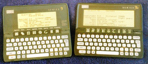
There are quite a few second-hand Series 3 Psions (and recently Series 3a and 3c Psions) available at bargain prices (usually from people who have upgraded to other Psions). StarTrak will run on the Series 3 as well as the 3a,3c, and 3mx Series, and there is a separate version for the epoc operating system, i.e. the Psion Series 5, Series 7, etc.
- Will StarTrak run on the Psion Series 5?
The version of StarTrak for the Series 3, 3a etc will not run on a Series 5 - there is a separate version of StarTrak for Symbian EPOC32 computers (the Psion Series 5, Series 7, Revo, Ericsson MC218 and others). This can be downloaded from the epoc32 download page.
- Will StarTrak run on the minimum spec 128k Series 3?
The 128k Psion Series 3 will run StarTrak, but only if the Startrak.opo executable file is located (and then run from) a flash memory card. This is to leave sufficient memory in the Psion to hold the star catalogue and enough free memory to run the application.
- Does StarTrak show the positions of the planets?
Yes. This functionality was added with release version 3.
- Do I have to keep adjusting StarTrak’s GMT setting as I move to different timezones?
Only if you’re adjusting the Psion clock to the local time in those timezones (e.g for your appointments diary), otherwise do not adjust the StarTrak GMT setting, even if you are observing the sky from different timezone locales.
- Under ‘Making Setting Circles’ there’s a photo of an azimuth circle. It appears that the cut-outs for the PTFE support pads are not symmetrical. Why is this?
I was rather sleepy when I cut this setting circle. We all make mistakes. The setting circle still works fine though, and with the rocker box on top no-one can see the cut-outs!
- Can I use ‘short-cut’ keystrokes instead of selecting from the menus?
Yes, but only on the Series 3…3mx range (not the epoc-based machines) - for example, to add or edit details of an observatory, with the ‘Psion’ key held down (bottom-left of Psion keyboard) press the ‘A’ key. This has just the same effect as selecting ‘Add/Edit’ from the Observatory group of menu options. The short-cut keystrokes are displayed on the menus.
- I notice that under the ‘Object’ group of menu options there is a ‘Find’ option. This seems to have the same effect as pressing the space-bar (to find another object).
Yes, that’s right. Since you will probably want to look at several objects during a night’s viewing, StarTrak was designed to make it easy to change the selected object, and so the space-bar was programmed as an additional ‘short-cut’ to the ‘Find’ option.
- How can I search for specific objects in the database?
An object in the database can be identified by any one of four possible alternative names - its Messier number (e.g. M13), NGC number (e.g. NGC6205), its common name (e.g. Aldebaran) or its ‘Bayer’ name (e.g. Alpha Tauri). These four alternatives are necessary because not all objects have Messier numbers, not all objects have NGC numbers, and so on. You can use ‘wildcard’ characters too - an asterisk means ‘any number of characters’, and ‘?’ means a single character. For example, if you are using the ‘List’ menu option, then nebula will list all the objects with ‘nebula’ (or ‘Nebula’) in their names.
- When I select the ‘About’ menu entry, it tells me that my copy of StarTrak “will expire on 1st January 2038.” Why?
The internal clock in the Psion 3 Series will stop updating programs from January 2038 - in other words, the Series 3 Psions were only ever designed to work up to this date. Quite possibly my Psion will still be working up to this date, and I hope I will too…
Perhaps there will be further updates to StarTrak over the coming years, but it’s more likely that StarTrak will be ported to a different kind of computer. Keep an eye on this website.
- Can StarTrak run on a PC?
StarTrak (the Series 3 version) can run on a PC if that PC has the Series 3 (or 3a etc) emulator, and if that PC is running one of the older versions of Windows. For example, I know the emulator works well with Windows 95 and 98, but appears to no longer work with Windows XP. A zipped copy of the Series 3 emulator program called S3emul.zip (written by Psion PLC) is available by clicking here.
Please note that neither ST Software nor Psion PLC (the authors of the emulator) can offer any support regarding installation and use of the emulator.
There is a different emulator for the epoc-based machines (Series 5, Series 7, etc) and this works with later versions of Windows too. You might need to search the web to track down a copy.
StarTrak: Making Setting Circles
From this site you can download a program which will help you to create setting circles. The program requires Windows 95, NT or later. The link (below) downloads the program as a self-extracting zip file called SETCIRCZ.EXE. After this has downloaded, double-click on its icon to extract the setting-circle program.
The program will print a large 90 degree protractor to assist in making an azimuth circle. The protractor is printed over 4 sheets of paper, which you then join together to give a protractor having a radius of over 360 mm. The program also prints a linear strip (to dimensions which you supply) graduated from 0 to 90 degrees. This is used for measuring altitude (if you have a Dobsonian mount, this strip can be fixed to the inside surface of the altitude pivot tube).
Large azimuth circle fitted beneath Cambridge Astronomical Association’s half-metre Dobsonian reflector
Some other ATM sites
Of course, you don’t have to use StarTrak to guide your telescope. Here are some very good websites from people who have used the setting circles program to design their setting circles for use with other star-finding software:
Rod Nabholz’s site: http://www.indytel.com/~rnabholz/twotube/index.htm
Two of Berislav Bracun’s sites: http://www.scopemaking.net/hrv/cald.htm and
http://www.scopemaking.net/300/300.htm.
…and for equatorial 'scopes…
(Here’s an extra program which you really don’t need if you have an altazimuth mount such as a Dobsonian. This extra program is for owners of equatorial telescopes, who wish to construct their own Right Ascension (RA) setting circle. This sort of setting circle is marked in hours and minutes, rather than in degrees. If you also want to create a Declination (Dec) setting circle for an equatorial telescope, please use the SetCirc program provided above - this is ideal for this purpose.)
Download RA Circle program.
(This link downloads the program as a self-extracting zip file called RACIRCZ.EXE. After this has downloaded, double-click on its icon to extract the RA setting-circle program.)
StarTrak - Construction tips
Here are some construction tips gained from adapting several telescopes for StarTrak use.
Tools
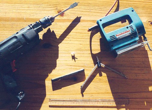
Here’s what you need:
a drill (preferably electric) and a drill-bit the same diameter as the telescope’s azimuth pivot, a jigsaw (an electric one makes the job much easier), a thumbtack (to help you mark out the azimuth circle), a permanent marker pen (with, say, a 0.3 or 0.5 mm nib), compasses for drawing a circle, and a rule marked in millimetres.
I guess if you want to be pedantic, you might ask “Where’s the glasspaper? And the pencil sharpener?” As you read on, it may occur to you that a paintbrush is also needed, and maybe a chunky screwdriver to open the paint can…
Preliminaries
Let’s assume that you have a Dobsonian telescope, and that it has large-diameter tubes for its altitude bearings. For measuring the altitude angle, you can create a linear scale (marked 0-90 degrees) to fix to either the inner surface or the outer surface (whichever is more convenient) of your 'scopes’s altitude bearing tube. (At another part of this website, you can see photographs illustrating this.) The SetCirc.exe program (which you can download from this website) can print such a linear scale. Please note that the SetCirc.exe program runs under Windows 95 / NT (or later releases of Windows), and does not run under other operating systems such as on a Mac or under Unix.
The length of the altitude scale strip needs to be one quarter of the circumference of the tube. (Here’s a further tip: measuring the inside circumference can be difficult, but here’s a trick to make it a lot easier. Acquire some thin plastic strip, for example the strip that hardware stores sell for ironing on to the sawn edges of melamine-faced chipboard. This can easily be curled up and fitted to the inside diameter of the altitude tube, then taken out, uncurled and measured to determine the inner circumference. Divide the distance by 4 and you have the required length of the altitude scale.)
Of course some scopes (particularly those made by the major manufacturers) don’t have the open-ended type of altitude bearing tube that allows a linear scale to be fitted in this way. Or maybe the altitude bearing tube has a diameter too small for a useful linear scale to be fitted. In such cases, it’s better to fit a circular scale (similar to the azimuth scale), though this means a little more work. See the photos of 'scopes for an example.
Creating scales from the SetCirc.exe program
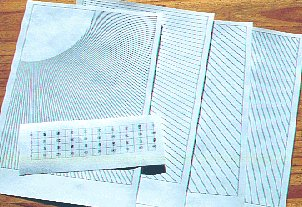
These are the templates created by the SetCirc.exe program (the program can be downloaded from this website).
When you run the program, the first stage is ‘calibration’, that is, determine the precise number of dots-per-inch (DPI) resolution of your printer (the calibration print is not shown in this photo). Based on the horizontal and vertical DPI figures you supply, the program prints what it thinks is a 100mm x 100mm square. When this is printed, measure the true width and height, and if not 100mm x 100mm, adjust your DPI settings accordingly.
If you want to see more detail, click on the photo.
When you have determined the printer’s DPI resolution accurately, you can accurately print the altitude scale and the template for the azimuth circle, as shown in this photograph.
The SetCirc.exe program creates four altitude scales, annotated in different ways. This gives you a choice (e.g. whether you wish the strip to be on the left-hand side of the 'scope, or on the right-hand side, on the inside or the outside of the altitude bearing tube).
For the azimuth template, the SetCirc.exe program prints four pages which you join together to make a large 90-degree protractor.
Cutting the azimuth circle
Here we see the limb extremities of a StarTrak devotee cutting an azimuth circle from some 2mm MDF (medium-density fibreboard). If you use an electric jigsaw this is quite an easy operation, and can be done quite accurately freehand - just follow the pencil line. Don’t cut the central hole (for the azimuth pivot) at this stage - this comes later. But be sure that you can find the centre point of the azimuth circle - there will probably be a tiny hole left by your compasses.
The azimuth circle will benefit from a few coats of paint. Based on experience, a first coat on each surface of quick-drying (acrylic) primer/undercoat, finished by a second coat on each surface of quick-drying (acrylic) gloss provides a very good finish. The board may warp a little after one surface has been painted, but applying a coat to the opposite surface will restore the board to being flat.
If you want to see more detail, click on the photo.
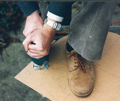
Marking the azimuth circle
When the azimuth circle is ready to have degree scales marked you can use the template from the SetCirc.exe program. Before using the template, draw two perpendicular diameters across the azimuth circle to divide it into quadrants. Cut the template to a smaller radius than the azimuth circle, and tape it to the azimuth circle.
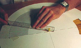
Insert the thumb-tack into the centre of the circle. Now take a rule or other straight edge and abut one end against the thumb-tack. Arm yourself with the marker pen and ‘extend’ the radial lines from the template out to the edge of the azimuth circle. The photo illustrates this well. From experience, this method of ‘extending’ the template markings is the best way to achieve good results. Not recommended is poking a pin through the template (to mark the azimuth circle underneath) - this technique gives inferior results.
If you want to see more detail, click on the photo.
Using a permanent marker pen will mean that the markings will not smudge if the azimuth circle gets wet, and the markings are unlikely to become faded by light.
Drilling the hole for the azimuth pivot
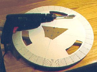
When all four quadrants have been marked, the last job on the azimuth circle is cutting the hole for the azimuth pivot.
Fix pieces of waste wood above and below the centre of the azimuth circle, and use the two perpendicular diameter lines to mark the centre of the circle on the piece of waste wood into which you will be drilling.
If you want to see more detail, click on the photo.
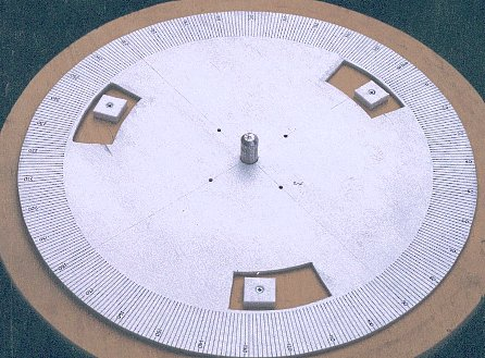
…and here’s the final azimuth setting circle, fitted to the base of the telescope. (Well actually it’s a different azimuth circle off another 'scope, but it illustrates the point).
If you want to see more detail, click on the photo.
Attaching the altitude scale
Before cutting the altitude scale, apply a strip of quality transparent tape to protect its surface. You make a neater job if you apply the tape before cutting the scale.
You can stick the altitude scale to the 'scope’s altitude bearing tube with some PVA-stick adhesive.
The last thing to do is to make some reference markers for the two scales. No hints or tips here, since this is quite straightforward, and details will depend on your scope. You need two markers attached to the rocker box - one near its base to mark the azimuth scale, and one near the altitude bearing tube to mark the altitude angle. That’s it!
Downloading the StarTrak program and database (for Psion Series 3 - 3mx)
The StarTrak program and database comprise four files which should be transferred to your Psion computer:
Stardata.odb
This file contains data on the night sky objects, such as name, magnitude, distance, and right-ascension / declination. This file must be located in the \OPD directory of the internal drive of your Psion.
Obsdata.odb
This file contains data on the observatory locations loaded in your Psion. This file must be located in the \OPD directory of the internal drive of your Psion.
Savedata.odb
This file contains data stored between observing sessions, for example the name of the last object you were observing, the name of the observatory, the time difference between the Psion clock and Greenwich Mean Time (GMT). This file must be located in the \OPD directory of the internal drive of your Psion.
Startrak.opo
This is the program which manages the database activities and computes the position of the selected objects from the chosen observatory. This program file would normally be located in the \OPO directory of the internal drive of your Psion, but you can keep it on a Flash SSD RAM module if you wish (the Flash SSD RAM module must then be inserted into the Psion for StarTrak to operate).
These four files can be downloaded to your PC as a single self-extracting zip file called Strakz.exe. After Strakz.exe has been downloaded, double-click on its icon to extract the four files destined for the Psion.
Download self-extracting zipped StarTrak software
If you have problems with the zipped version (above), try downloading the uncompressed files individually (see list below).
If you are using Internet Explorer 5, you may find that it has an annoying habit of renaming files as it downloads them (so Stardata.odb is renamed to Stardata.odb.odb, for example). If this happens, just accept the renaming during the download then rename the downloaded files back to their correct names before transferring them to the Psion.
Stardata.odb
Obsdata.odb
Savedata.odb
StarTrak.opo
To transfer the four files from your PC to your Psion, you will need the necessary connection cable and software (such as PsiWin) from Psion. However, if several people wish to use StarTrak on their Psions, once the necessary files have been loaded onto one Psion (e.g. using PsiWin), then StarTrak can be copied from one Psion to another via a Flash RAM module.
StarTrak user manual
This manual describes the StarTrak computer program, running on a Psion Series 3, 3a, 3c or 3mx pocket computer. The purpose of StarTrak is to assist astronomers in locating objects in the night sky - especially if using an altazimuth mount telescope such as a Dobsonian.
Revised for version s3.08, April 2003
ST Software
http://www.startrak.co.uk
Contents
Chapter 1
What is StarTrak? What does it do?
What StarTrak doesn’t do
Starting StarTrak
Using the Esc key
Using the Menu key
Exiting from StarTrak
Automatic powerdown
Chapter 2
Setting up StarTrak for your timezone
‘Real’ time and ‘Fixed’ time
Setting up StarTrak for your observatory
Selecting other observatories
Listing the observatories
Chapter 3
Selecting an object in StarTrak
Listing the objects in the database
Setting up your telescope
Pointing the telescope
Using the Esc key
Chapter 4
Adding objects and editing objects
Exercise: editing an object’s details
Exercise: adding object NGC2403
Exercise: adding object Beta Canis Majoris (Mirzam)
Finally…
Appendix 1: Object types known to StarTrak
Appendix 2: Objects in StarTrak database
Appendix 3: Constellation names
Appendix 4: Loading StarTrak on to your Psion
Download User Manual
The StarTrak User Manual (for Psion Series 3 - 3mx) can be downloaded as a self-extracting zip file (which can self-extract under Microsoft Windows or DOS). When the download is complete, double-click on the Man6z.exe or Man97z.exe icon - it will then self-extract to give the StarTrak User Manual in Microsoft Word format.
Download StarTrak User Manual (Word 6 / 95 format)
Download StarTrak User Manual (Word 97 format) (much smaller file size than Word 6 / 95 format. Suitable for later versions of Windows.)
Return to StarTrak home page
Greenwich Mean Time
According to your computer, Greenwich Mean Time is Mon, 09 Jul 2007 06:38:15 GMT. The accuracy of this setting depends on the setting of your computer’s clock, and whether your computer is set to the correct timezone.This screen updates every 10 seconds, or whenever you refresh the screen.
Universal Time, UTC (which is effectively the same as Greenwich Mean Time, GMT) may be read from the atomic clock at the U S Naval Observatory. The web site is
http://tycho.usno.navy.mil/what.html
You should expect it to be a few seconds late because of the time taken to transmit through the Internet.